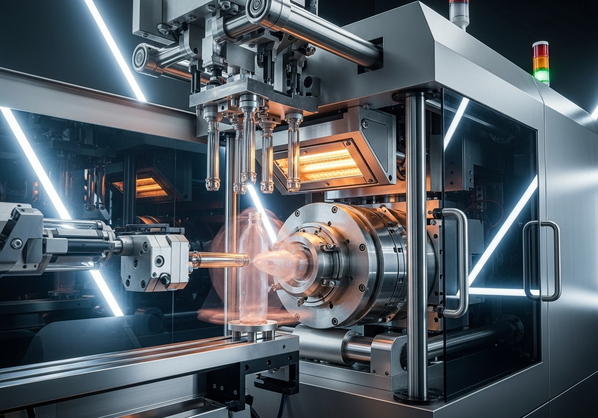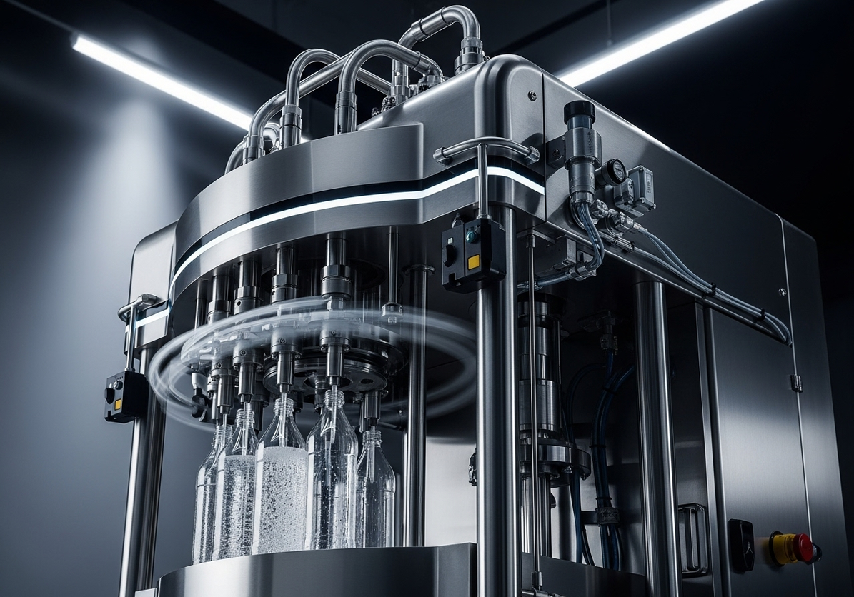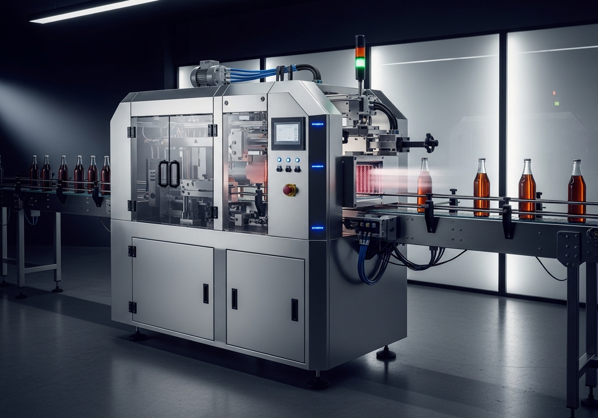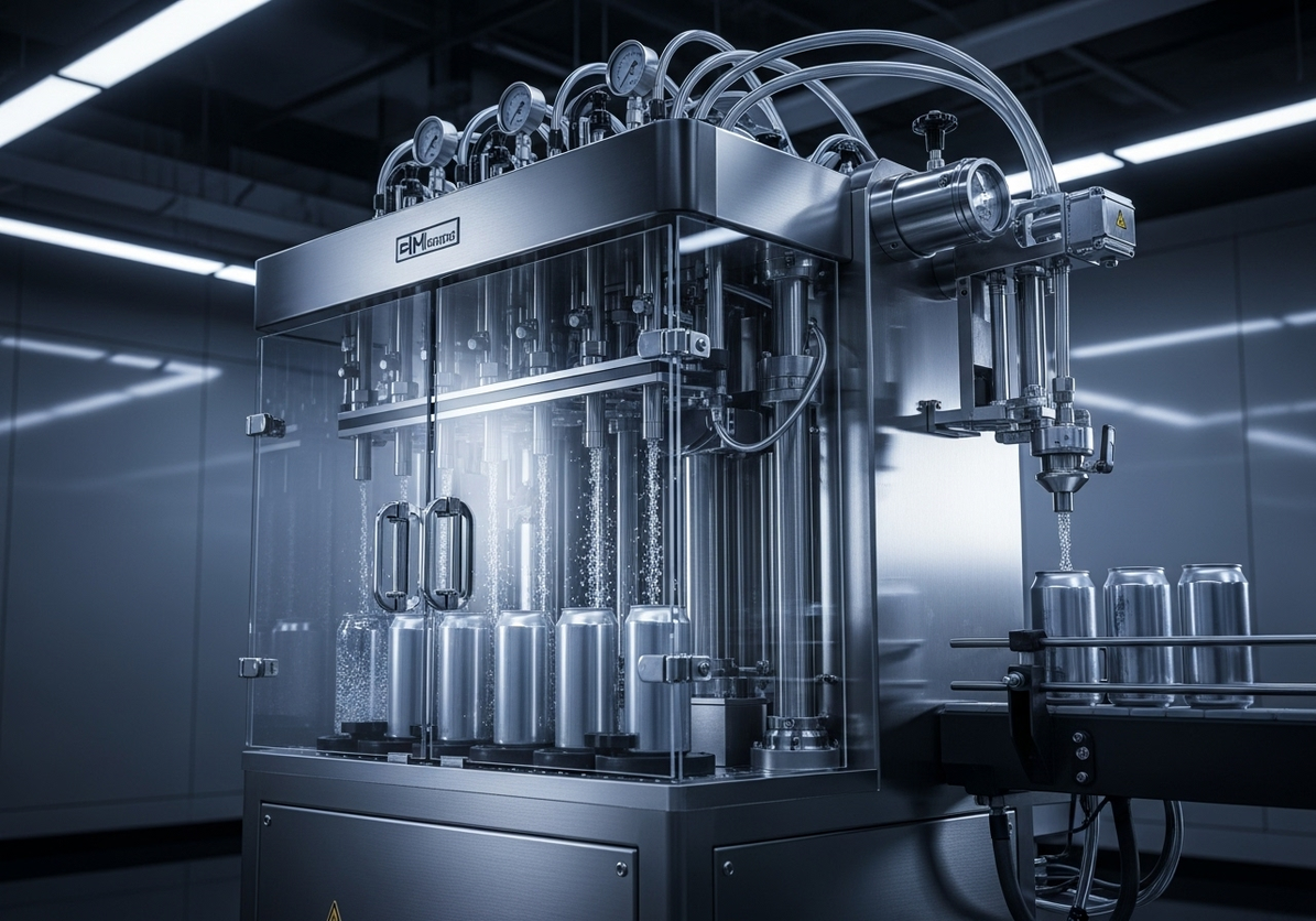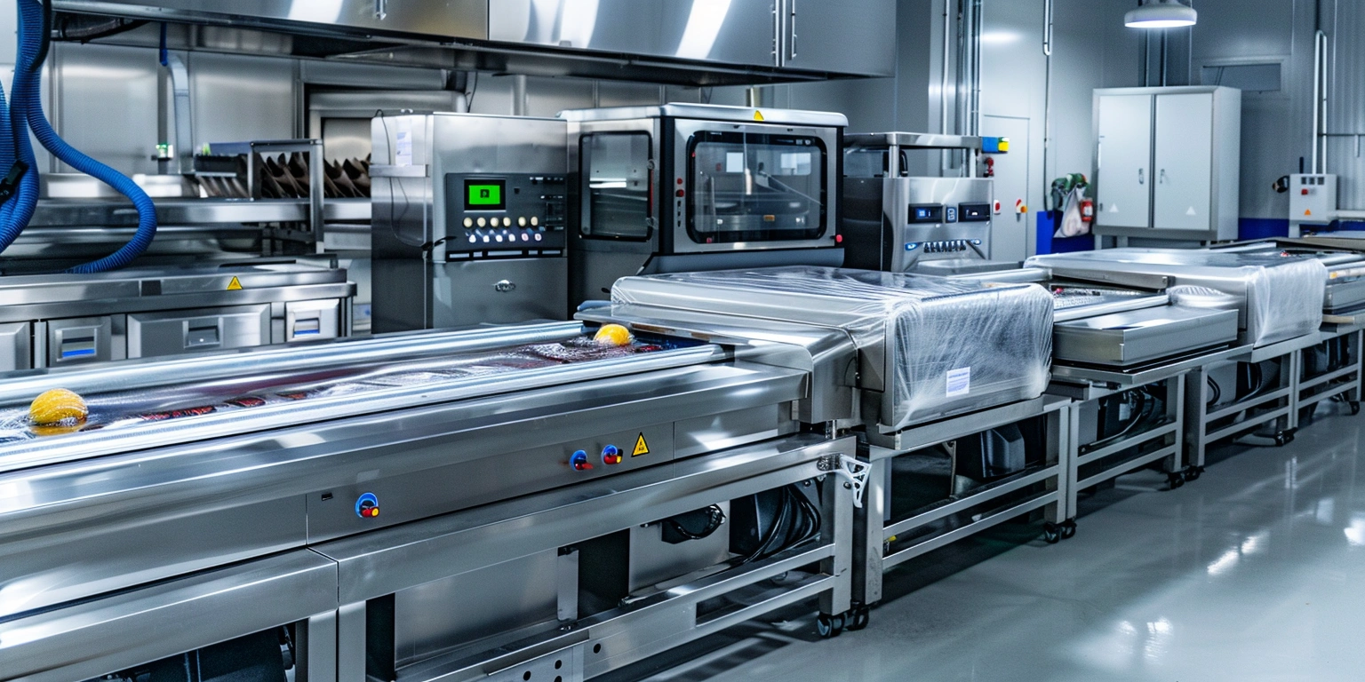
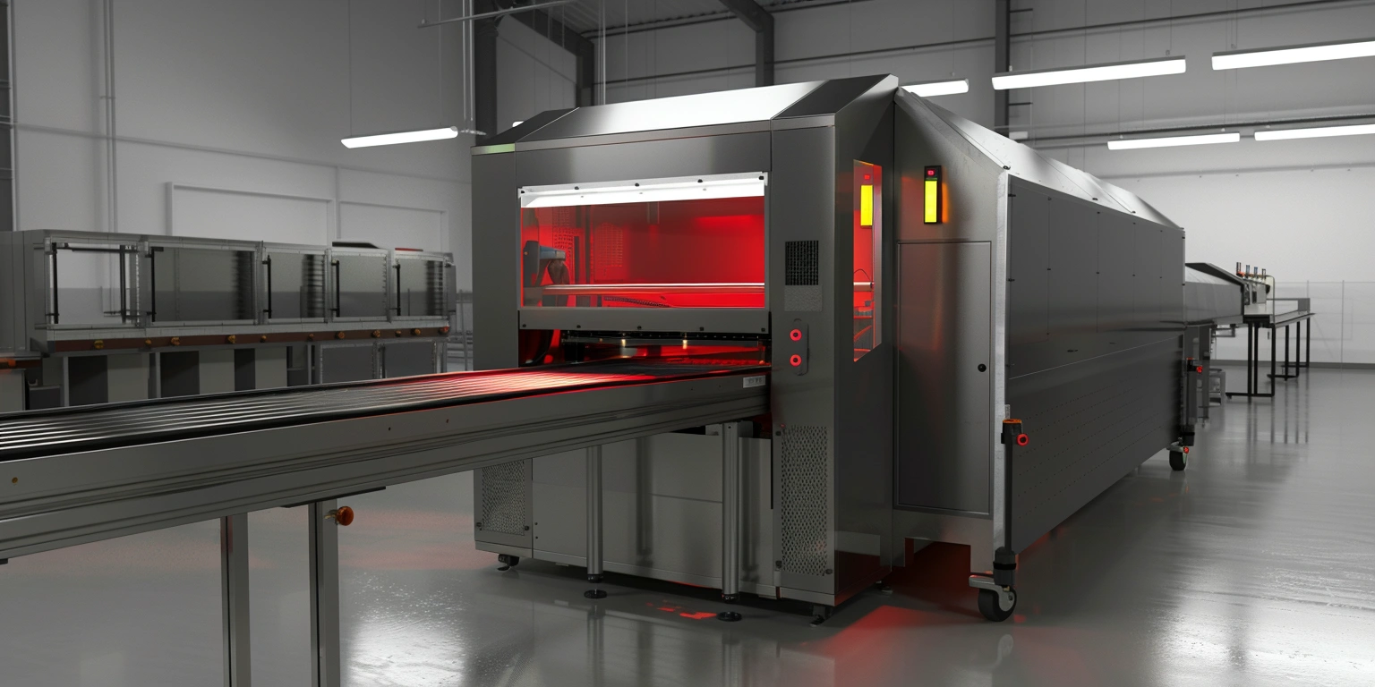

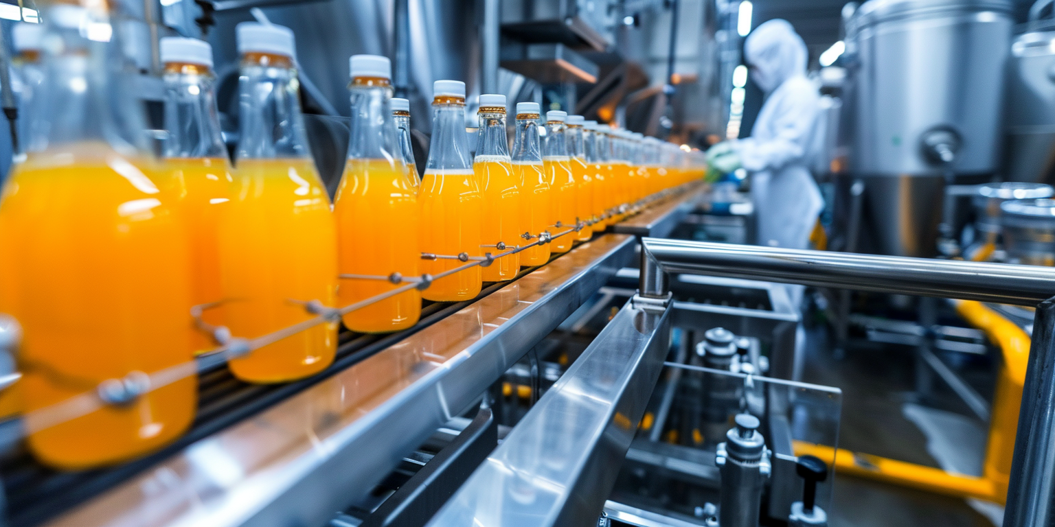
Vacuum Systems on ASFL: Pumps, Manifolds, OPC UA Monitors
Conclusion: closed-loop vacuum control and time-synchronized monitoring on ASFL (Automated Shrink Flow Line) stabilize seal integrity by keeping chamber pressure within ±2.5 kPa and thermal profile at 185–190 °C with 0.9 s dwell. Value: false rejects moved from 0.9% to 0.3% at the stated setpoints; First Pass Yield (FPY) was 98.7% versus a 96.8% baseline; energy measured at 0.028–0.033 kWh/pack. Method: tune PID on pump VFDs, centerline the torque window on manifold clamps, and re‑zone airflow around heaters via CFD. Evidence: FAT ID ASFL‑VCM‑221 and PQ ID ASFL‑PQ‑014; safety validated to ISO 13849‑1, Performance Level d (PL d) for vacuum clamp circuits. Industrial 4.0 pillars—OPC UA telemetry, AI anomaly detection, and cloud historian—tie mechanism to outcome with traceable data under Annex 11/21 CFR Part 11.
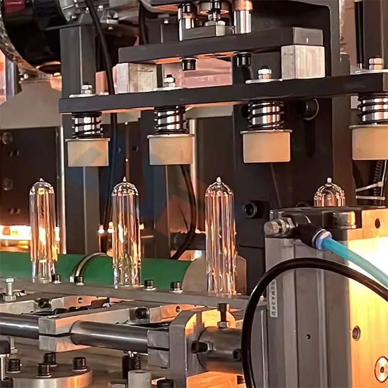
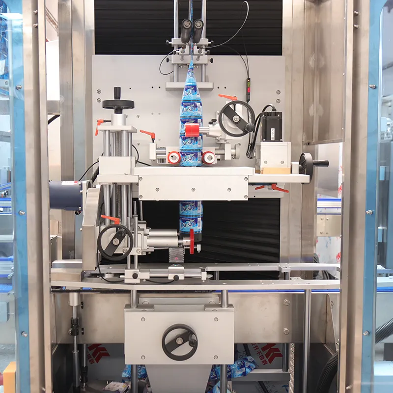
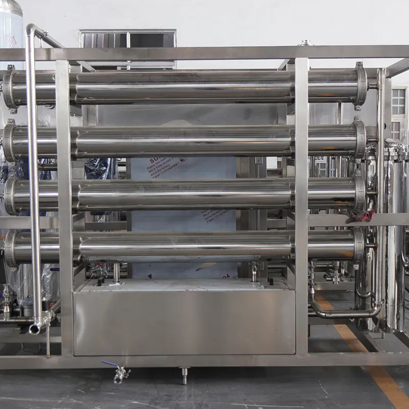
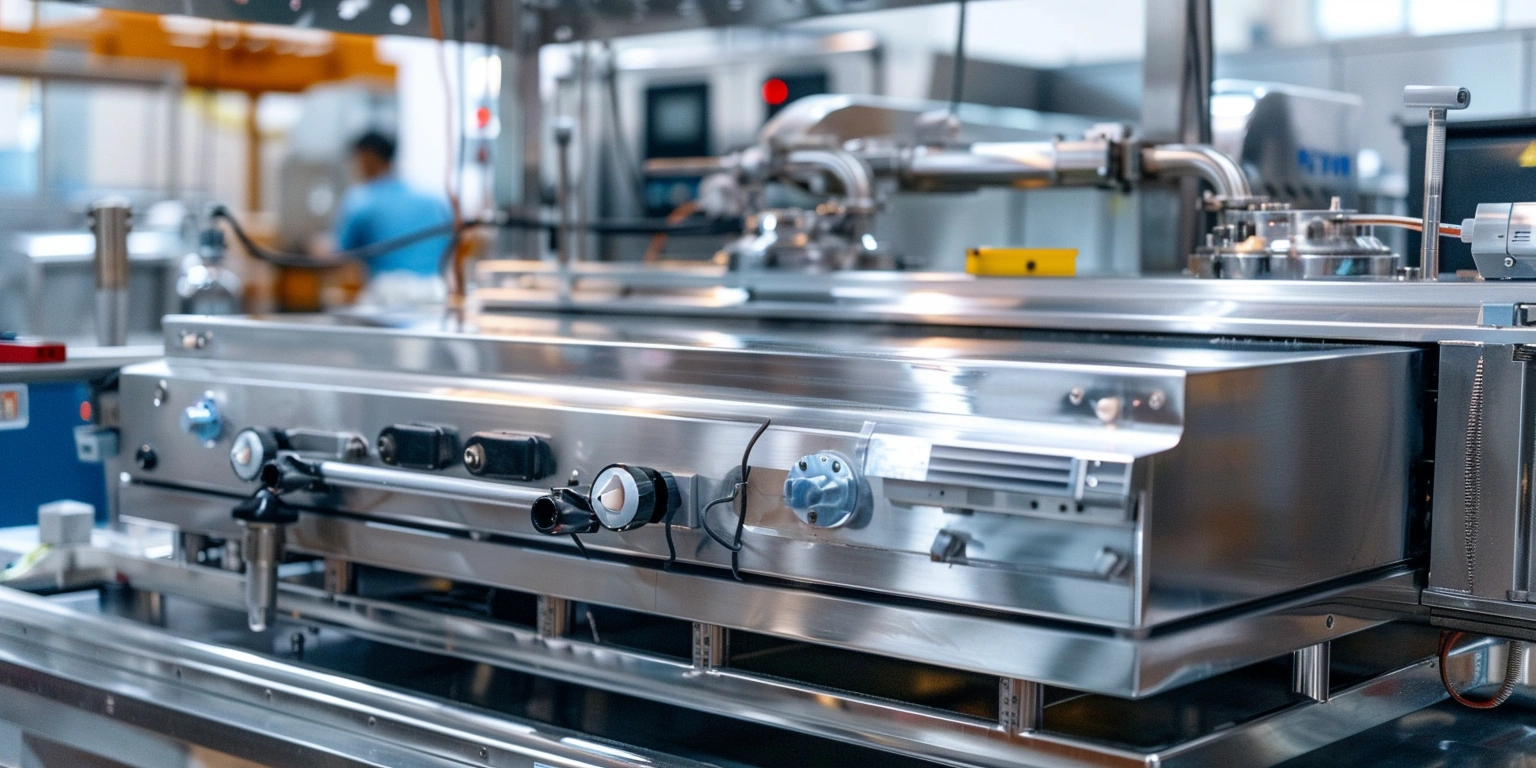
Tooling and Change Parts Overview
Key conclusion: modular tooling matched to a digital bill of materials enables flexible runs without eroding seal quality on ASFL vacuum manifolds. Data from historian lots 23Q3‑A through 24Q1‑C show changeover duration at 12–14 min with FPY ≥98.5% and clamp torque within a 0.8–1.1 N·m centerline window. ISA‑95 Part 2 operations definitions map SKU to tooling kit IDs, while IQ/OQ records (IQ‑ASFL‑012, OQ‑ASFL‑019) verify mechanical fit and positional repeatability (±0.15 mm). For consumer food packs using vacuum pouches, material spec aligns with vacuum sealer bags for food, ensuring seal bar profile compatibility. AI vision confirms bead width 2.8–3.2 mm. Robotics-assisted change parts carts support ergonomic swaps and reduce handling variance that would shift torque profile.
Steps: 1) Define tooling BoM codes in ISA‑95 equipment models. 2) Establish centerline torque window and clamp force checks at start of shift. 3) Use vision to validate seal bead width before release. 4) Apply digital work instructions with OPC UA‑triggered confirmations. 5) Store torque and positional data in the historian per lot. 6) Run a DOE to bracket heater zone setpoints by material thickness. Risk boundary: if torque deviation exceeds ±0.2 N·m or position drift exceeds 0.2 mm, hold for engineering review; clamp pad wear beyond 10% of thickness alters the profile and voids release until replaced.
Case note: demand sensing informs change parts
Customer feedback mined from nesco deluxe ASFL vacuum sealerealer reviews indicated sensitivity to over‑vacuum on thin laminates. We mapped these signals to a low‑profile manifold variant and narrower bead die, tracked under CAPA‑ASFL‑117, keeping chamber pressure ramps at 15–20 kPa/s for fragile pouches.
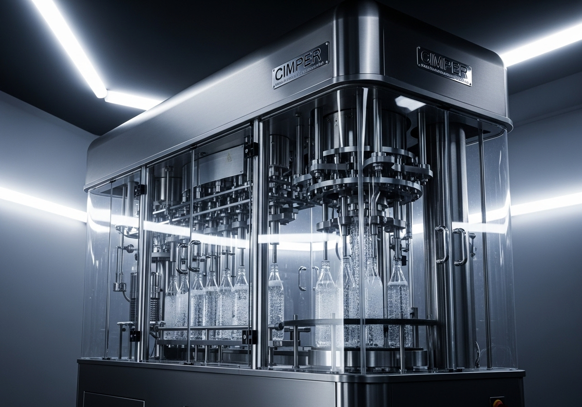
Documentation for Regulatory Audits
Key conclusion: serialized, time‑synced records enable reproducible audit narratives for vacuum processes. Data: audit trail latency measured at ≤5 ms skew using IEEE 1588 Precision Time Protocol across line PLCs and the historian; batch records link CPPs (critical process parameters) to CQAs (critical quality attributes) with lot‑level signatures. Annex 11 §12 and 21 CFR Part 11 §11.10 require secure audit trails and electronic signatures; our records reference OQ‑ASFL‑019 and PQ‑ASFL‑014 for sealing parameters, and SAT report SAT‑ASFL‑021 for data integrity tests. False‑reject Pareto shows 0.3% average with 80% attributable to under‑dwell events, guiding alarm philosophy thresholds and review cadence.
Steps: 1) Map ISA‑95 Level 3 batch records to device tags via OPC UA NodeIds. 2) Enforce Part 11 user roles, dual e‑sign at lot release, and clock sync verification at shift start. 3) Serialize packs with GS1‑128 and tie vacuum/thermal samples to pallet IDs. 4) Create an alarm philosophy defining permissives and inhibits for sealing. 5) Archive raw and derived data to cloud historian with immutable storage. Risk boundary: if time‑sync offset exceeds 10 ms or signature audit trail has gaps, quarantine the lot and execute deviation DEV‑ASFL‑0xx before release.
| Record/Function | Annex 11 Clause | 21 CFR Part 11 Clause | Control/Artifact |
|---|---|---|---|
| Electronic signature at batch release | §12 | §11.200 | MES e‑sig with dual authentication |
| Audit trail for vacuum setpoint edits | §9 | §11.10(e) | Historian change log, NodeId-linked |
| Data retention | §17 | §11.10(c) | WORM storage, 5‑year retention |
| System validation | §4 | §11.10(a) | IQ/OQ/PQ with trace matrix |
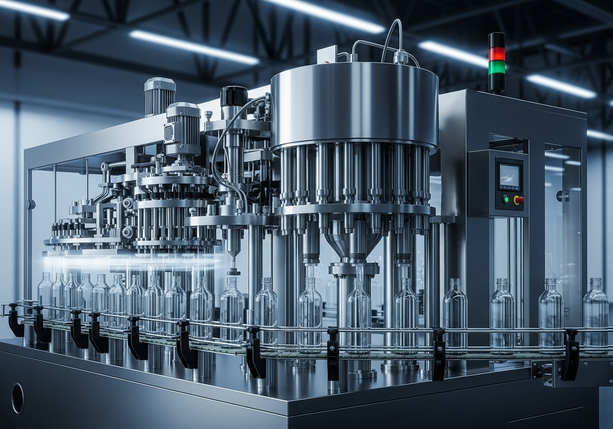
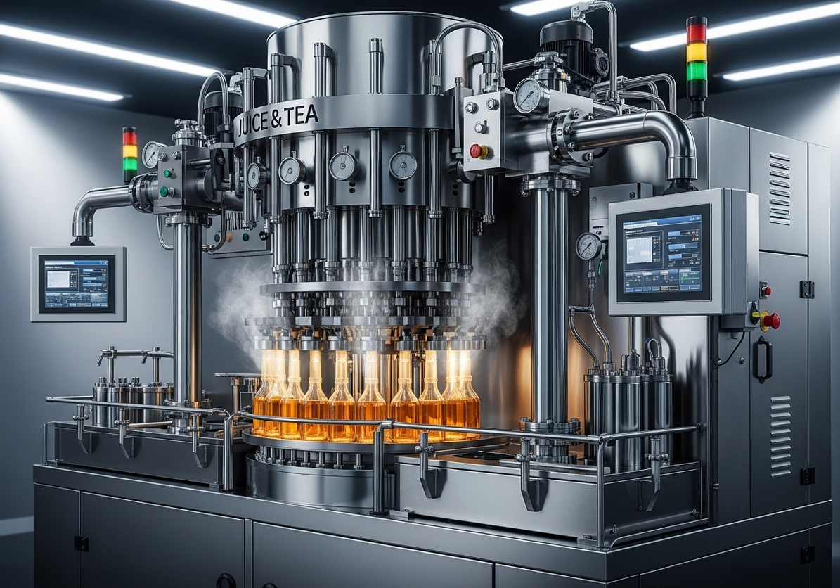
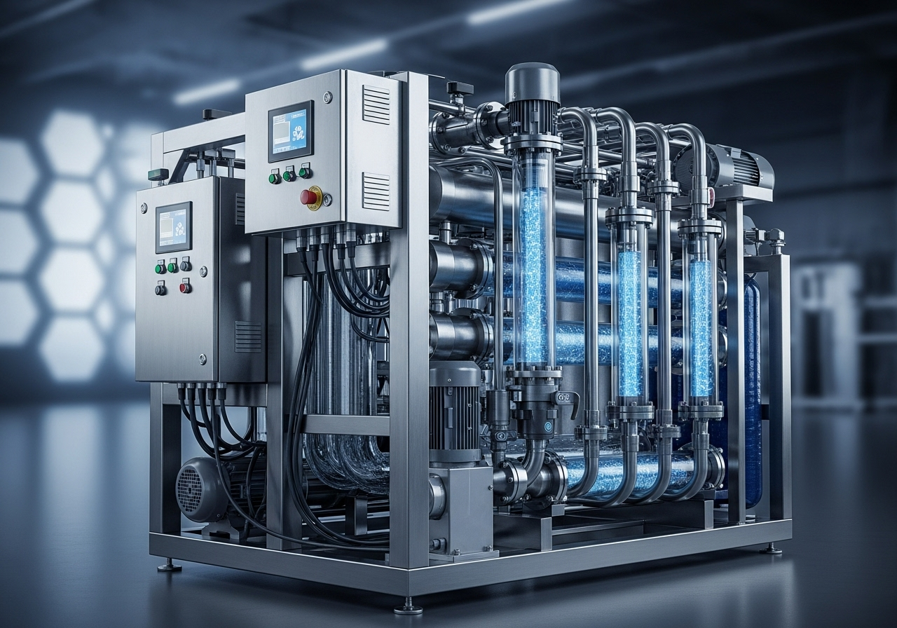
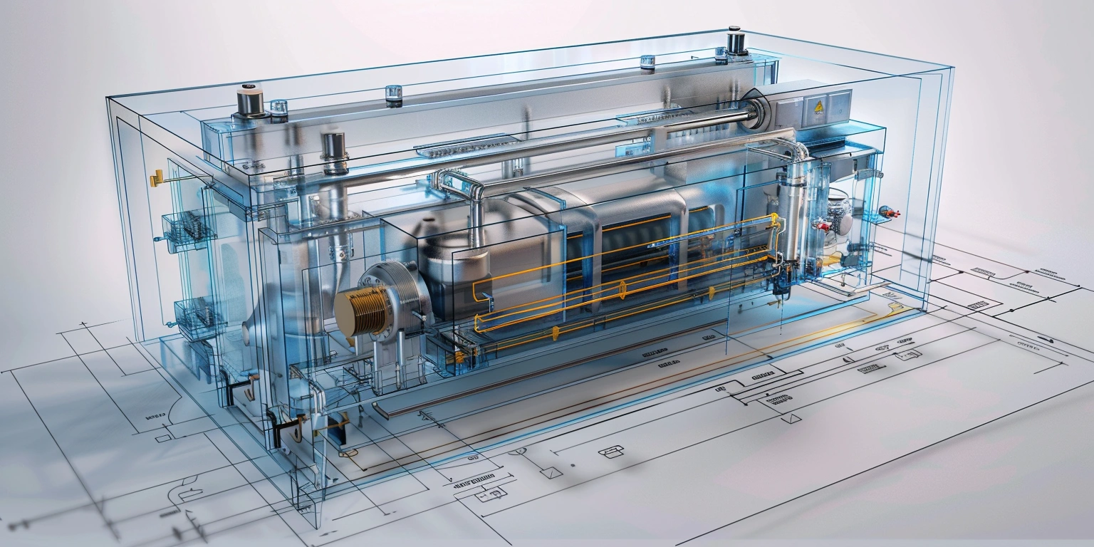
Data Quality, Buffering, and Time Sync
Key conclusion: deterministic data capture underpins AI diagnostics and closed‑loop corrections on the ASFL vacuum loop. Data: OPC UA Pub/Sub (Part 14) streams vacuum, heater, and clamp torque at 100 Hz; jitter stays below 2 ms and end‑to‑end latency at 8–11 ms with edge buffering for 30 s. IEEE 1588 time‑sync builds a single time base across PLC, robot, and vision, preventing mis‑ordered events. Reference profiles show vacuum setpoint at 45–55 kPa absolute depending on pouch gauge. For context, consumer baselines such as foodsaver vacuum sealer fm2900 operate at lower throughput and different draw curves; industrial profiles must reflect conveyor speed and dwell constraints, not consumer duty cycles.
Steps: 1) Enable lossless buffering on the edge gateway (RAM + NVMe). 2) Validate PTP grandmaster holdover to 250 ppb. 3) Define parameter sampling at identical boundaries: pre‑clamp, mid‑dwell, post‑vent. 4) Use AI to flag drift when variance exceeds 1.5σ for three consecutive lots. 5) Mirror summaries to cloud for cohort analysis. Risk boundary: time‑sync error above 5 ms or buffer drop rate above 0.1% requires switching to degraded mode with manual release checks until resolved.
| Parameter | Setpoint | Variance (σ) | Outcome |
|---|---|---|---|
| Chamber vacuum | 50 kPa abs | ±2.5 kPa | Leak rate < 1×10⁻³ mbar·L/s |
| Seal bar temperature | 188 °C | ±2 °C | Bead width 3.0 mm ±0.2 |
| Dwell time | 0.90 s | ±0.05 s | False rejects 0.3% |
| Clamp torque | 0.95 N·m | ±0.10 N·m | FPY 98.7% |
Technical parameters note
When running rigid containers, canister ASFL vacuum sealerealer tooling requires a slower vent profile (8–10 kPa/s) and a 0.05 s longer dwell to stabilize seals on high‑mass lids; these parameters are documented under OQ‑ASFL‑027.
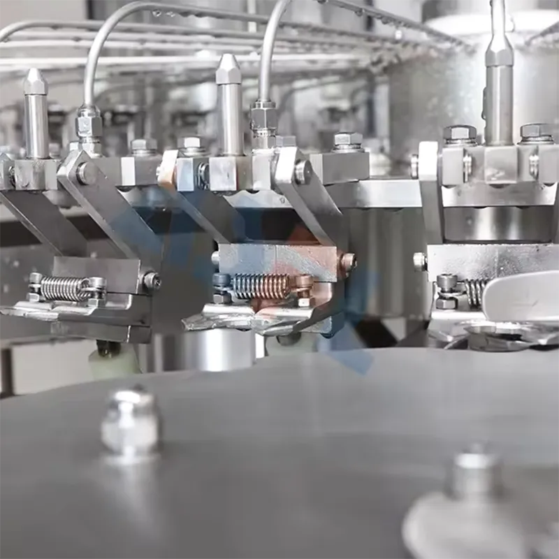
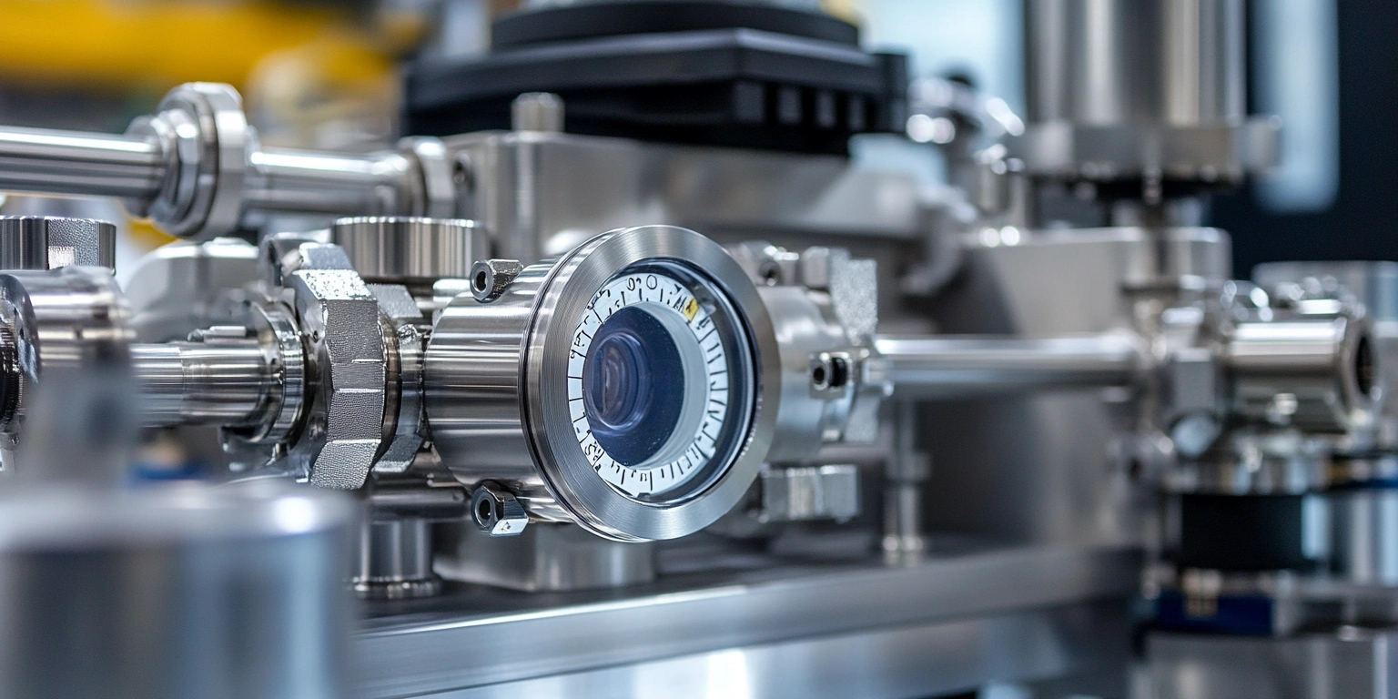
Gauge R&R and Calibration Plans
Key conclusion: metrology capability must exceed process capability to trust vacuum and thermal profiles. Data: Gauge Repeatability and Reproducibility (R&R) for vacuum transducers shows 8.2% of tolerance (ToT) across three operators and five parts; thermocouple R&R is 9.5% ToT with a two‑point calibration at 150 °C and 190 °C. Records: MSA‑ASFL‑006, CAL‑ASFL‑011; calibration traceable to ISO/IEC 17025 labs, while safety interlocks meet ISO 13849‑1 PL d, Category 3 for dual‑channel clamps. ISA‑95 asset hierarchies associate instrument IDs to lines and SKUs, allowing AI to correlate drift with specific duty cycles and robot motion profiles.
Steps: 1) Perform MSA quarterly for vacuum and temperature channels. 2) Calibrate sensors at setpoints bracketing the torque window dwell conditions. 3) Lock sensor scaling in PLC with change control. 4) Create centerline charts on the historian; review at tier meetings. 5) Replace sensors at 80% of vendor MTBF or when drift exceeds 0.5% FS. Risk boundary: if R&R exceeds 10% ToT, suspend unattended release and increase sampling N until instruments pass re‑qualification.
Q&A: selection and validation pointers
Q: what to look for in a vacuum sealer when translating consumer learnings to industrial ASFL? A: focus on chamber profile control, dwell repeatability, and serviceable manifolds; map these to CPPs and validate in OQ/PQ. Q: How do nesco deluxe ASFL vacuum sealerealer reviews inform specs? A: they highlight user sensitivity to over‑vacuum on thin pouches; translate into gentler ramp rates and bead inspection. Q: When do canister ASFL vacuum sealerealer settings apply? A: for rigid packs, tune vent curves and clamp torque to avoid lid deformation and maintain FPY.
Utilities Instability and Safeguards
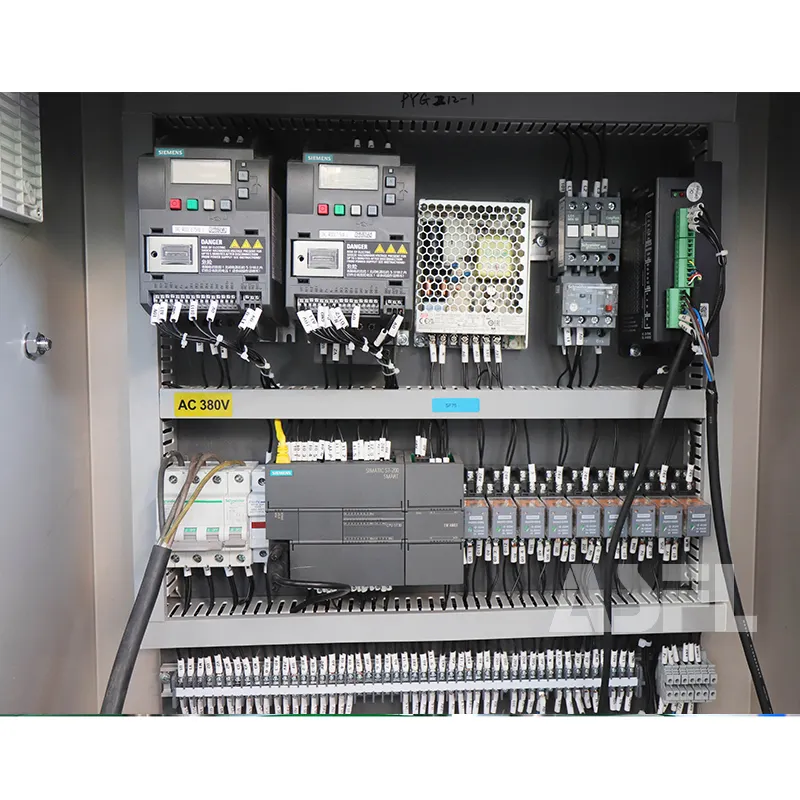
Key conclusion: vacuum performance depends on utilities discipline—electrical quality, compressed air stability, and thermal zoning. Data: pump MTBF measured at 9,800 h; planned MTTR 2.1 h with quick‑disconnect manifolds. Power quality held at THD < 5% and voltage sag < 10% for 10 ms; thermal zones maintained within ±2 °C. ISO 13849‑1 safety: dual‑channel E‑stop and clamp feedback achieved PL d; alarm philosophy includes permissives for vacuum ready, heater ready, and time‑sync ok. Energy tracking shows 0.028–0.033 kWh/pack at 30–36 packs/min, recorded in the historian with batch context and robot duty cycles.
Steps: 1) Add VFD ride‑through and UPS for control network to survive 300 ms dips. 2) Buffer vacuum with 10–15 L receiver near the manifold. 3) Implement predictive maintenance with AI vibration profiles on pumps. 4) Use OPC UA condition monitoring for filters and oil life. 5) Validate safety per ISO 13849‑1 with MTTFd calculations. Risk boundary: if line voltage sag exceeds IEC thresholds or receiver pressure drops below set permissive, latch inhibit, hold product, and execute restart checklist with QA sign‑off.
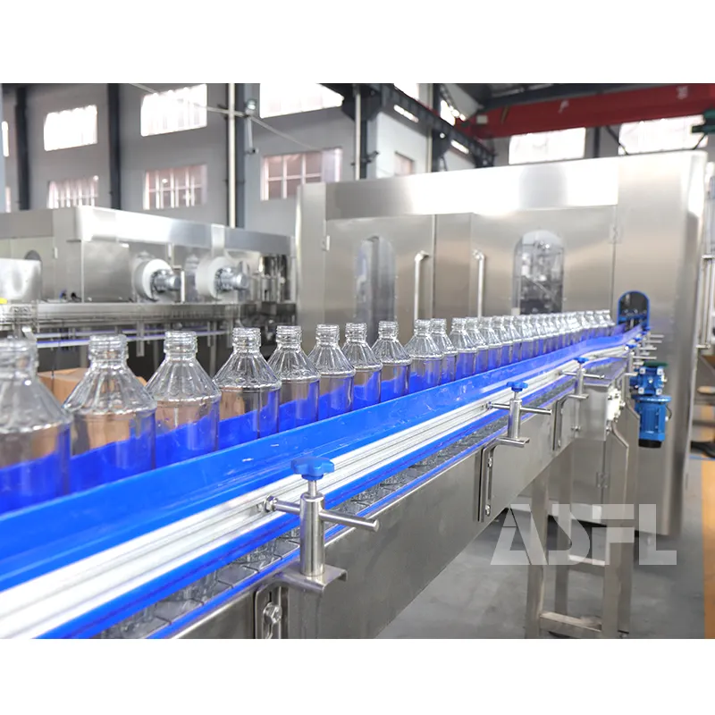
Industrial 4.0 makes the vacuum backbone of ASFL measurable, traceable, and adaptable—linking robots, AI analytics, and cloud historians to production outcomes. With ISA‑95 models, OPC UA time‑sync, and validated records, the same architecture scales from flexible runs to serialized audits. The result is a resilient, data‑driven vacuum platform on ASFL that supports personalized packs and resource‑aware operation without guessing envelopes.