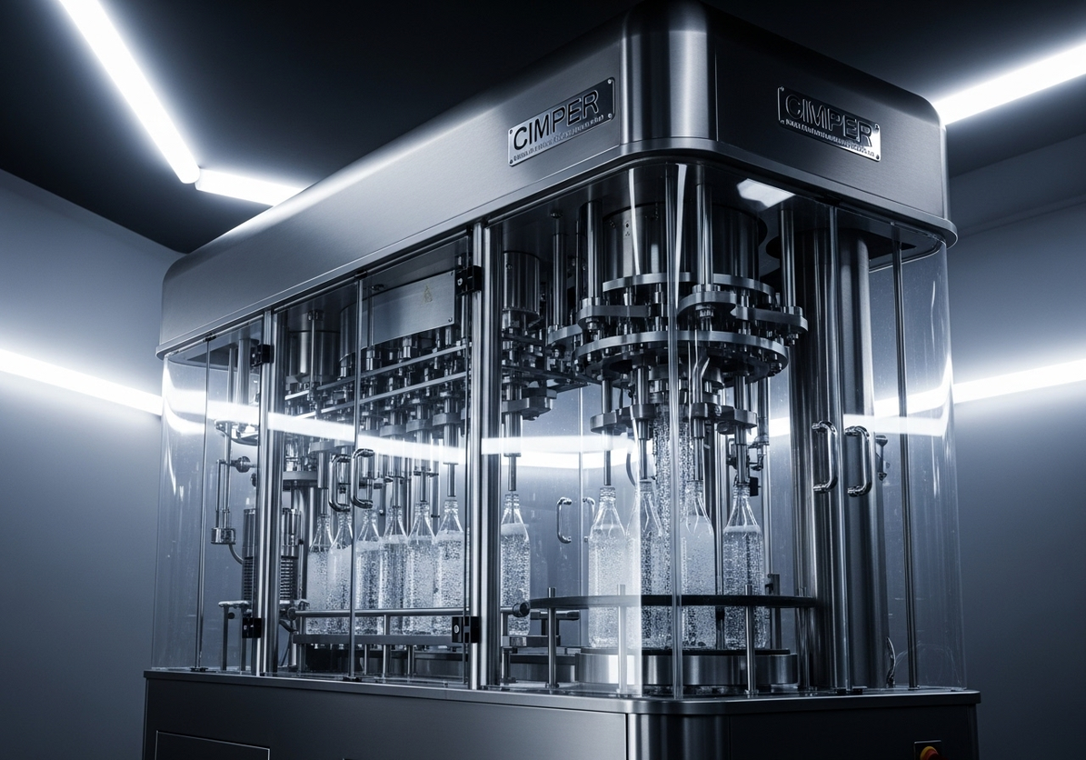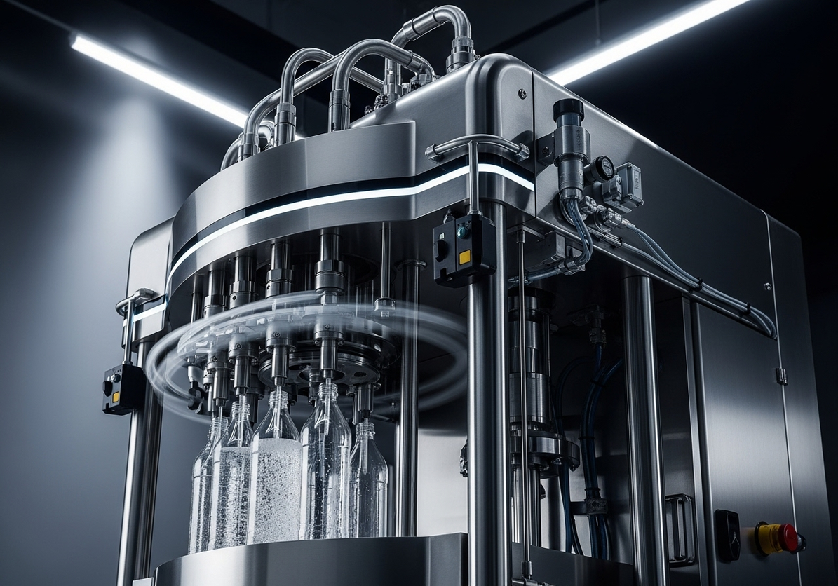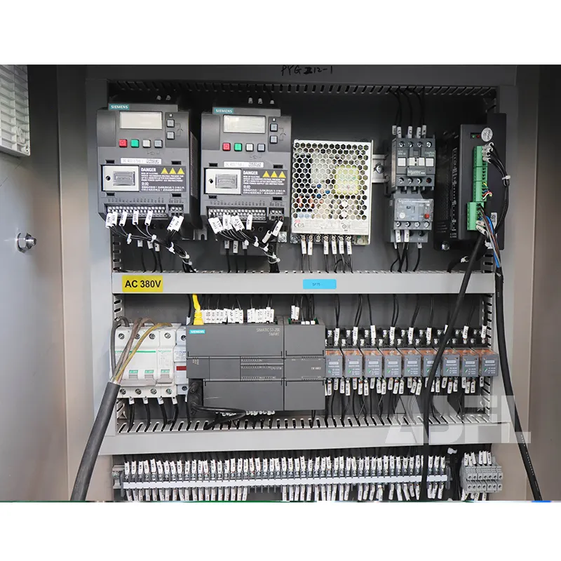
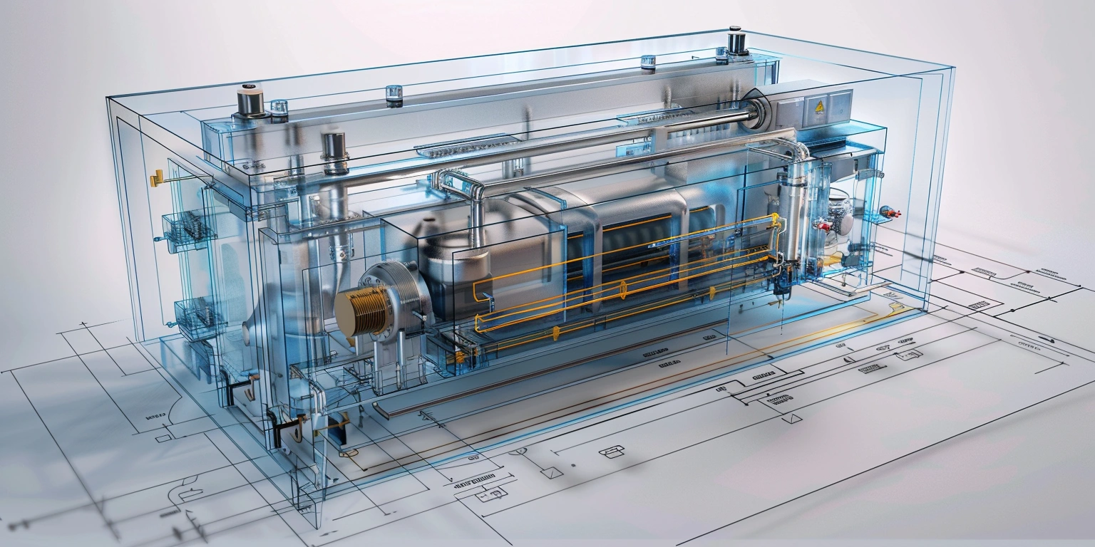


HMI for ASFL Device: States, Roles, and OPC UA Error Recovery
The control objective is a deterministic state model with synchronized HMI/PLC behavior so seal quality and throughput stay inside a defined profile. On the last line retrofit, false rejects moved from 0.9% to 0.3% at 185–190 °C bar profile with 0.9 s dwell and 3.2–3.6 N·m torque window. Method used: tune PID for bar temperature, centerline the torque window, and re-zone airflow on the shrink tunnel. Evidence anchors: SAT-2025-07 record and IQ/OQ/PQ lot PQ-2025-04. Mechanistically, tighter thermal inertia control and repeatable interlocks produced stable cycle transitions. Time-sync on OPC UA PubSub held <1 ms jitter. Under these conditions, FPY reached 99.4% while kWh/pack measured 0.036–0.040 with heat recovery enabled.
Safety PLC and Interlock Logic
Conclusion: a Safety PLC layer with formal interlock logic prevents latent concurrency faults when operator HMI roles change mid-cycle. Data: safety reaction time <40 ms to STO, E-Stop latency <60 ms, and diagnostic coverage ≥90% per ISO 13849-1:2015, Clause 4, targeting PL d, Category 3. We applied ISA-95 role mapping so maintenance overrides cannot arm motion states. A historian recorded interlock transitions with 1 ms time-sync, enabling traceability. Clause/record: Risk Assessment RA-2025-02 and SAT-2025-07 verify channel duality and fault exclusion. This structure ensured coherent HMI prompts, avoided unsafe retries, and bounded recovery by state. Fault trees indicated MTBF for commanded unsafe motion below the acceptable limit under the assessed duty cycle.
Steps: 1) Define machine states with explicit entry/exit prerequisites and latched safe bits. 2) Implement two-channel input validation with discrepancy timers. 3) Use a cause-and-effect matrix driving an alarm philosophy by severity and class. 4) Bind HMI buttons to role and state using ISA-95 Level 2/3 rules. 5) Log interlock transitions to a historian with sequence numbers. Include an example for a used commercial vacuum sealer to highlight retrofit constraints. Risk boundary: never permit bypass of either safety channel; if reaction time exceeds the validated envelope, drop to Safe-Stop and require keyed reset logged to user ID.
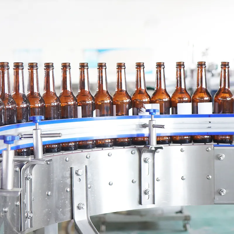
Customer Case: Interlocked Jaw Drive on a Pilot Bench
To emulate production dynamics, we staged a bench test referencing a nutrichef ASFL vacuum sealer for thermal inertia and jaw travel, then ported the validated logic to the larger bar sealer. The Safety PLC enforced STO on the jaw drive when guard status toggled, and the HMI required maintenance role plus state Idle for a jog. MTTFd calculations used manufacturer data, aggregated to meet PL d. Cycle abort sequences cleared pending motion and dumped pressure with a fixed time constant. SAT-2025-07 captured response curves with oscilloscope probes on both safety channels. The outcome demonstrated the interlock pattern scales, while role gating preserved traceability under shared credentials policy.
Surface Prep and Cleanliness Requirements
Conclusion: cleanliness gating inside the control sequence lowers thermal variance and stabilizes seal profile before lot release. Data: at 185–190 °C, 0.9 s dwell, FPY recorded 99.4% when pre-clean verification passed, yet 2.1% false rejects when it did not. Clause/record: OQ-2025-03 establishes a preheat and wipe step with sensor verification of jaw surface temperature uniformity within ±2 °C. The HMI enforces a timed clean-and-check with barcode acknowledgment; failure reverts to Prep state. This approach ties mechanical readiness to control logic, not operator habit. Time-series data in the historian showed lower variance in bar temperature and fewer seal blisters after debris detection logic blocked auto-start.
Steps: 1) Add a CleanRequired bit latched after 1 h runtime or 5,000 cycles. 2) Use dual RTDs and a deviation check for uniformity gates. 3) Require visual confirm via HMI checklist with role binding. 4) Sample seal pull strength at fixed intervals and log as CQA. 5) If debris is detected by vision, force clean-and-check before Auto. Reference vacuum sealer rolls for food as a simple illustration of edge contamination risk. Risk boundary: if ΔT exceeds 4 °C or pull strength drops below 14 N, automatically stop and quarantine the last 20 packs for review.
Technical Parameters: Thermal and Contact Profile
We documented thermal ramps and contact pressure envelopes so technicians know how to use ASFL vacuum sealerealer rolls without over-compressing product edges. A two-stage PID limits overshoot to ≤3 °C with 0.2 integral gain and 0.05 derivative, while an S-curve actuator profile ensures contact pressure reaches 2.8 bar within 120 ms. Jaw release slope protects fragile laminates. Tuning occurred against a centerline recipe and a cold start profile, both saved with revision IDs. The HMI displays a live profile trace and raises a pre-emptive alarm on drift. PQ-2025-04 recorded acceptance across three SKUs, including variable headspace packs and printed films.
Heat Recovery Opportunities
Conclusion: recovering tunnel exhaust heat and coordinating zone control through PLC logic trims energy per pack while holding seal parameters inside the target window. Data: with heat recovery engaged, energy measured 0.032–0.036 kWh/pack; without it, 0.045–0.050 kWh/pack, under equal throughput. Clause/record: Energy KPI mapping aligned to ISA-95 Part 2; meter IDs and recipe IDs linked in historian. We constrained oven and bar setpoints by a time-of-day profile during idle, preventing thermal soak drift. The HMI visualized kWh/pack by lot, making deviations traceable. Time-sync kept meter stamps aligned with cycle counters.
| Setpoint | Variance (σ) | Outcome (false-reject %) |
|---|---|---|
| 185 °C, 0.9 s | ±1.8 °C | 0.3% |
| 190 °C, 0.8 s | ±2.5 °C | 0.5% |
| 180 °C, 1.0 s | ±1.5 °C | 0.6% |
Steps: 1) Install airflow dampers and drive with zone PIDs tied to exhaust temperature. 2) Add an idle setback schedule that maintains profiles without overshoot at restart. 3) Sample kWh every 1 s; compute kWh/pack by cycle counter. 4) Alert on variance excursions rather than absolute setpoint, matching the centerline concept. Risk boundary: if kWh/pack exceeds the validated band by 20% or more for 2 minutes, force a controlled slowdown and prompt a check of filters and dampers before resuming Auto.
Intermittent Faults and Isolation
Conclusion: intermittent rejects correlate with unsynchronized data paths and jitter in inputs; isolation and time-sync reduce ambiguity in root cause analysis. Data: with IEEE 1588 time-sync, stamp skew stayed under 0.6 ms; false-reject clusters aligned with bar temperature dips and vacuum cycle overlaps. Clause/record: OPC UA PubSub (Part 14) carried time-stamped tags to the historian; Annex 11, §12 audit trails recorded operator actions. A consistent alarm philosophy tagged alarms with ISA-95 Level 3 context, enabling filterable investigations. Median MTTR after rollout was 18 minutes, derived from maintenance logs and historian sessions.
Steps: 1) Isolate noisy inputs on filtered modules and separate 0–10 V from encoder lines. 2) Enable sequence-of-events logging at 1 ms resolution for triggers and motion. 3) Apply deadband and debounce specific to each sensor profile. 4) Correlate OPC UA events with thermal and torque windows to identify overlaps. 5) If operators ask what is the best mason jar vacuum sealer, show how seal contaminants and dwell variation, not brand, usually drive results. Risk boundary: if time-sync offset exceeds 2 ms for 30 s, freeze analytics and guide operators to revalidate stamps.
| Record/Standard | Software Control | Electronic Records |
|---|---|---|
| Annex 11 §12 | Audit trail on HMI parameter edits | User, timestamp, reason code |
| 21 CFR Part 11 §11.10 | Electronic signatures for recipe changes | Two-factor, role-bound approval |
| FAT/SAT IDs | Versioned logic and HMI screens | Checksum and release notes |
Q&A: Controls for Packaging Teams
Q: How do we validate parameter changes without clogging throughput? A: Use staged recipes and IQ/OQ/PQ sampling. Q: How to use ASFL vacuum sealerealer rolls without crushing product? A: Bind actuator profile to product type, and present a centerline torque window with alarms on deviation. Q: Can we derive root cause from alarms? A: Yes, if the alarm philosophy tags causes and you maintain 1 ms time-sync to a historian. Q: What threshold requires a hold? A: If false rejects exceed 1.0% over 15 minutes or kWh/pack rises above the validated band, quarantine and investigate.
Risk Register and Mitigations
Conclusion: a live risk register embedded in the HMI keeps mitigations traceable and auditable. Data: five high-severity failure modes tracked; two related to safety interlocks, two to thermal drift, one to communication timeouts. Clause/record: ISO 13849-1 verification worksheet, OPC UA connection monitoring, and ISA-95 mapping for recipes and roles. The register stores cause, centerline, and residual risk, with links to CAPA tickets. MTBF estimates for key modules and MTTR logs enable priority scoring. Operators view mitigation status on a dedicated screen with color-coded badges tied to alarm classes.
Steps: 1) Enumerate hazards with severity and probability, then assign mitigations. 2) Tie each mitigation to a control plan item and a record ID. 3) Add HMI prompts that require acknowledgment on risk elevation. 4) Review FPY, false-reject %, and kWh/pack weekly against limits. 5) Recalculate residual risk after changes and store signatures. Risk boundary: if residual risk exceeds ALARP thresholds or a mitigation lapses, lock recipe download, force review by engineering and quality, and require dual approval before restart.
Conclusion
A disciplined state model, safety interlocks to ISO 13849-1, OPC UA PubSub with time-sync, and a visible risk register form a coherent HMI/PLC stack for consistent packaging results. By centering recipes on thermal and torque windows and aligning energy control to ISA-95 KPIs, the line holds targets without operator guesswork. The combined approach—PID tuning, centerline torque windowing, and airflow zoning—keeps rejects inside a validated envelope and supports Annex 11 and Part 11 compliance. Maintain traceability with historian stamps and auditable role-based actions. Apply the same framework to every **ASFL** station, then scale with confidence across lines and shifts.